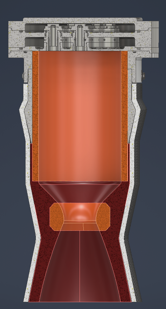
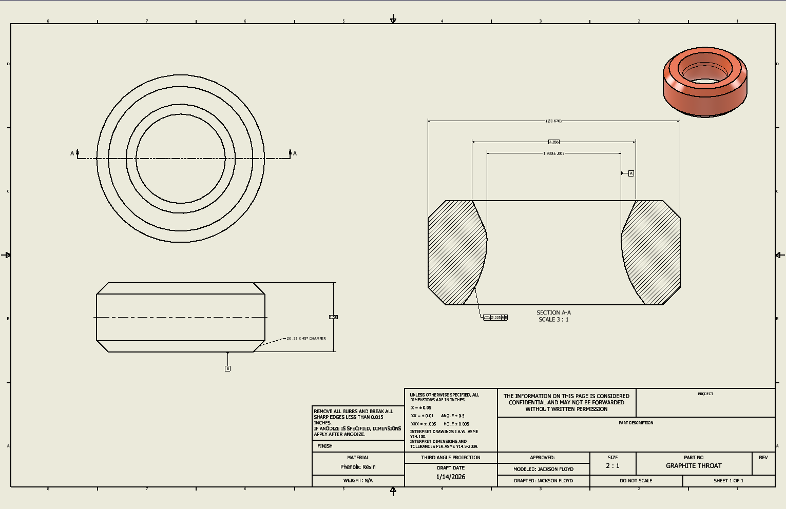
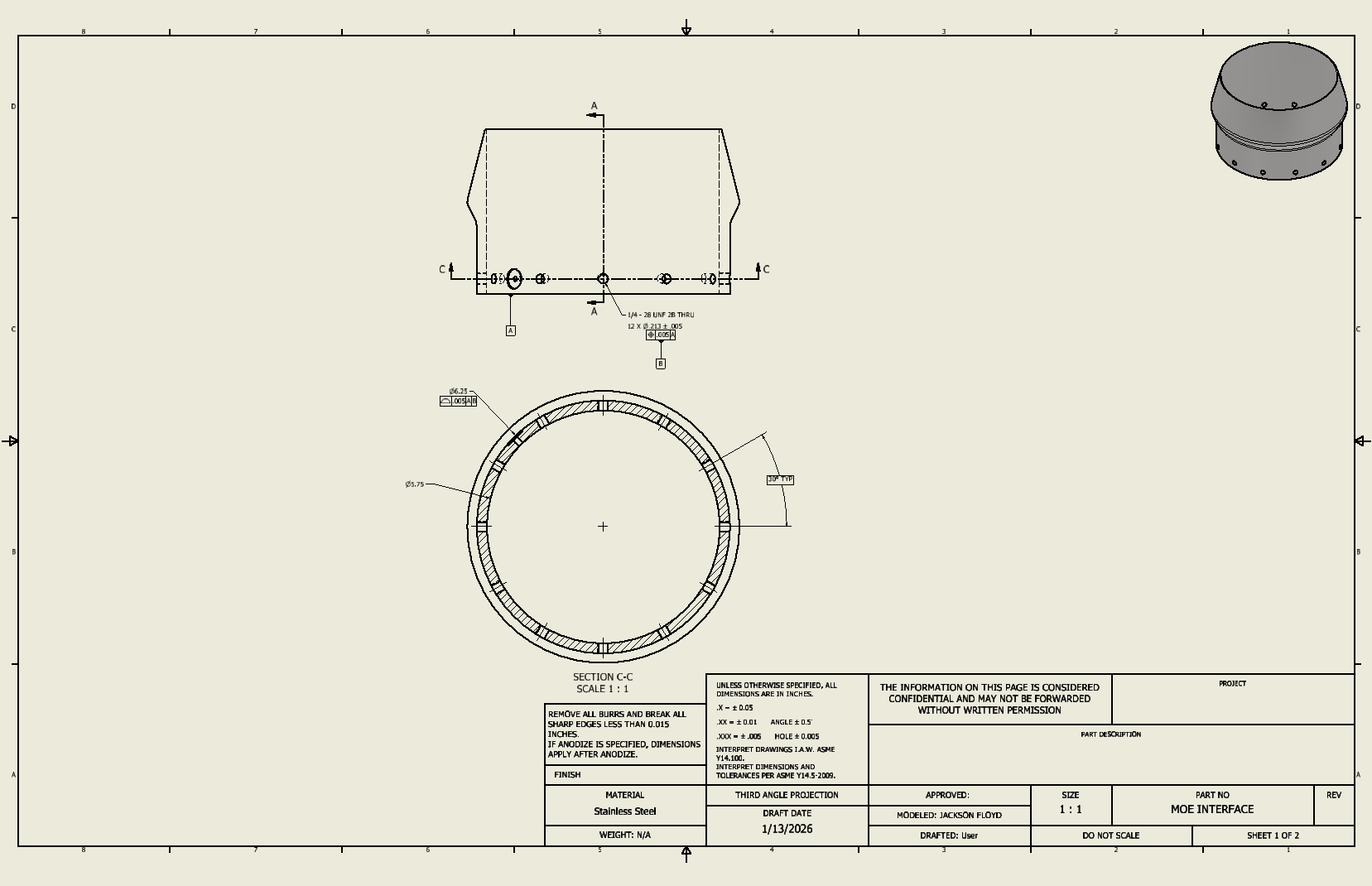
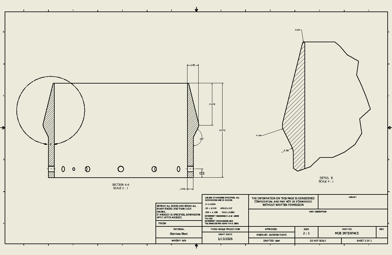
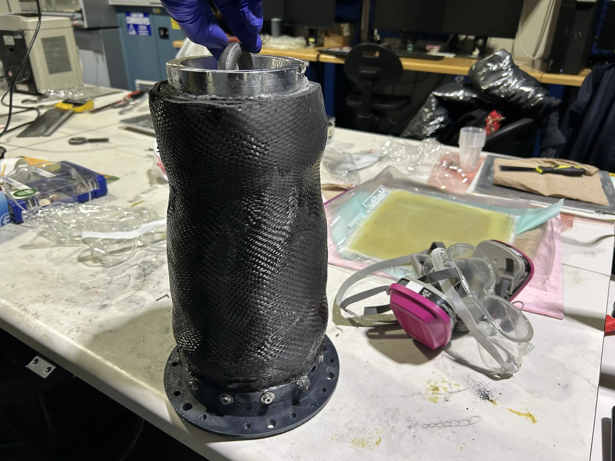
This cross-section shows the major parts of the engine assembly. The engine features the same injector and injector mount as on the old engine. However, the injector mount was re-machined to fashion the composite retention ring. In addition a phenolic chamber and throat insert were used in critical areas to limit ablation over the 15-second burn time.
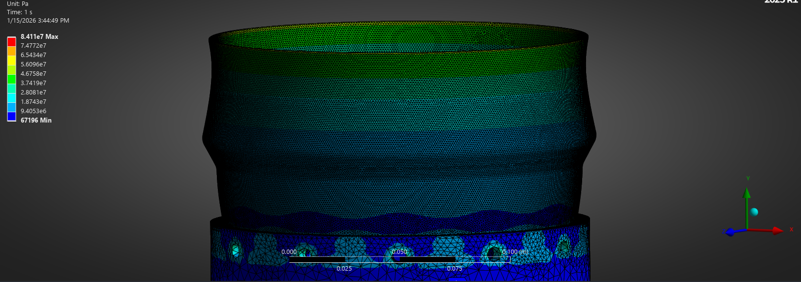
Analysis of the composite retention ring using Aluminum 6061-T6 showed a sufficient factor of safety proven through FEA and hand calculations, with a 500psi chamber pressure and 2250lbf thrust acting on the piece equating to roughly 7700lb acting axially across the area of the ring. The hoop stress felt by the ring is also partly carried by the carbon fiber overwrap; however, this part is not shown in the FEA.
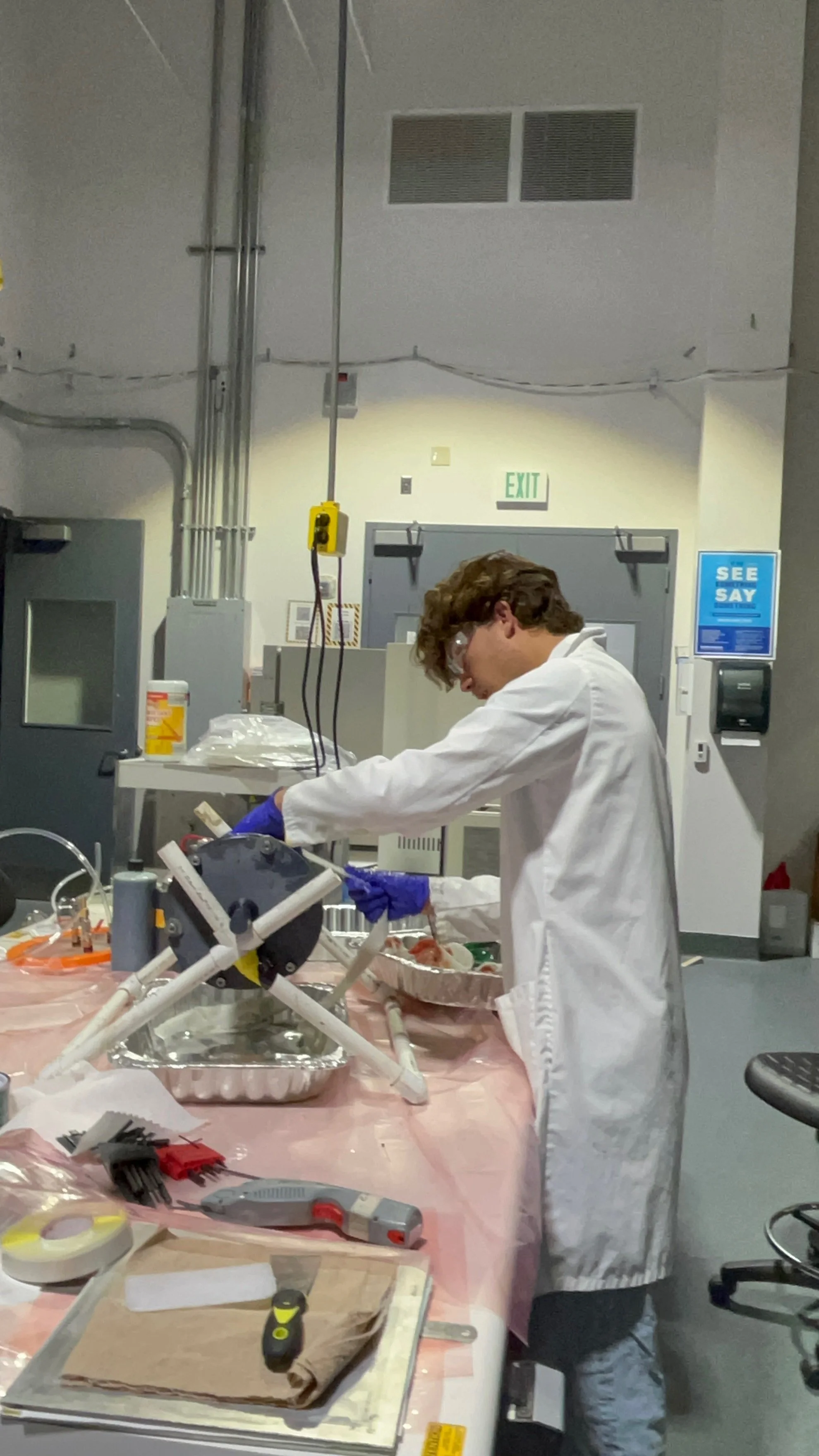
Initial Tests
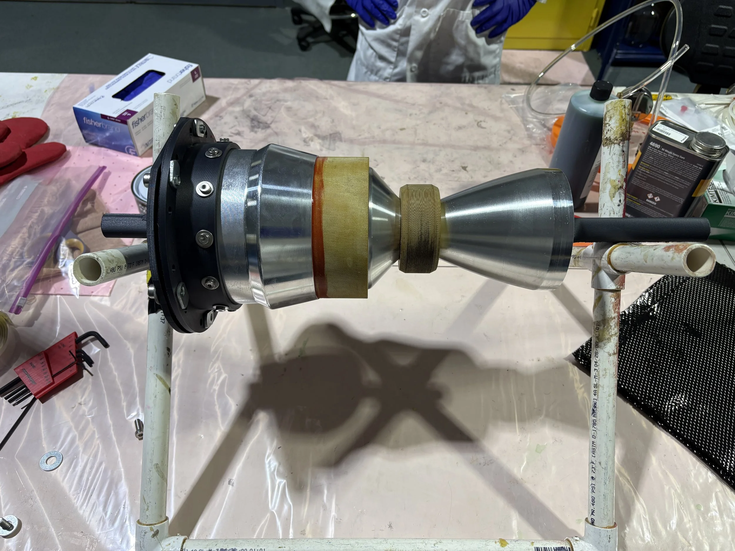
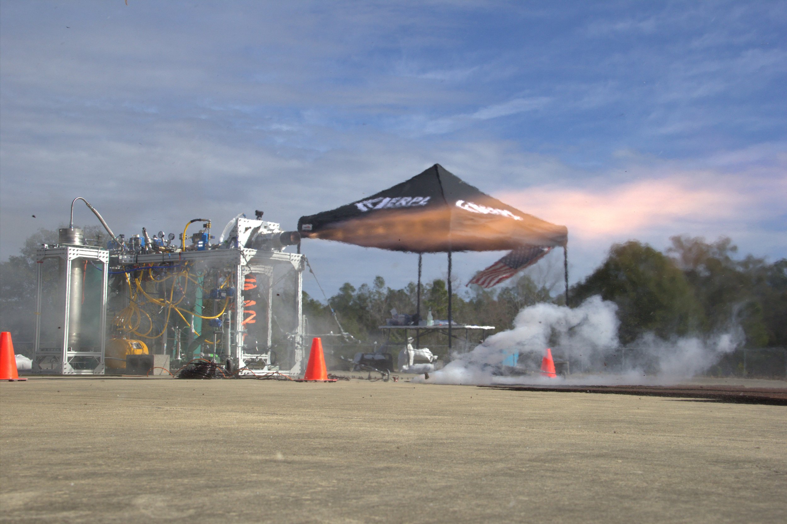
Initial water flow and hot fire tests of MOE were made using an engine engineered by the class before the current leadership. The engine features a swirl injector, a phenolic chamber, and an experimental graphite nozzle retained by a metal ring.
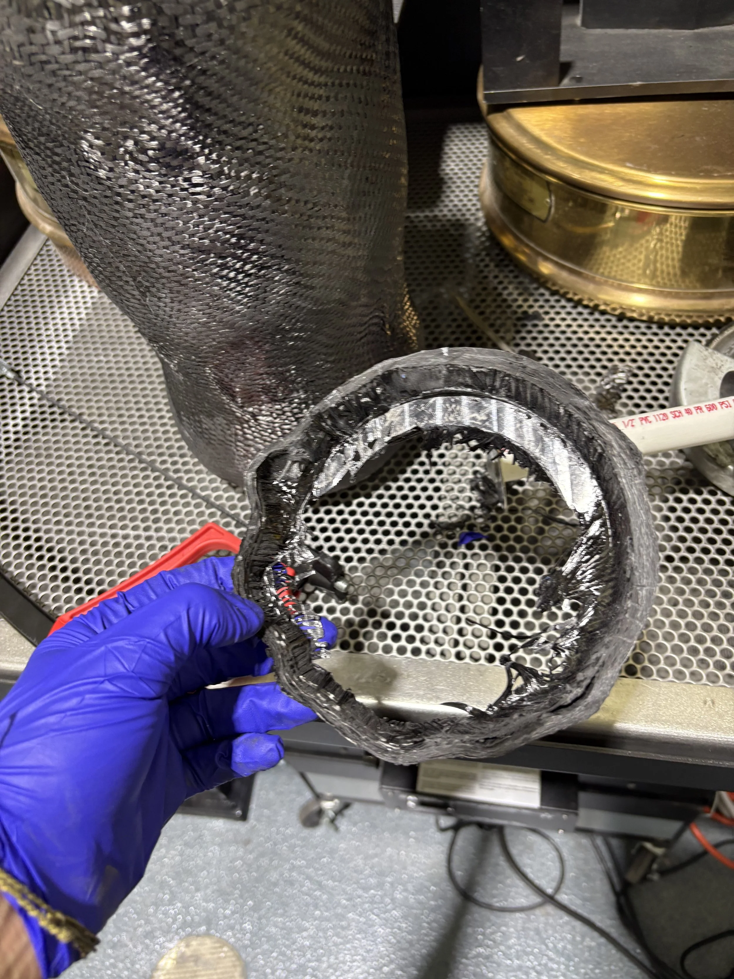
The graphite had been a big concern to the club and me, as the material is notoriously bad at handling shear stresses. This concern was later realized as 4 seconds into the hot fire, the engine’s nozzle ejected, breaking clean at the sharp angle created by the retention ring. This confirmed our hypothesis of shear.
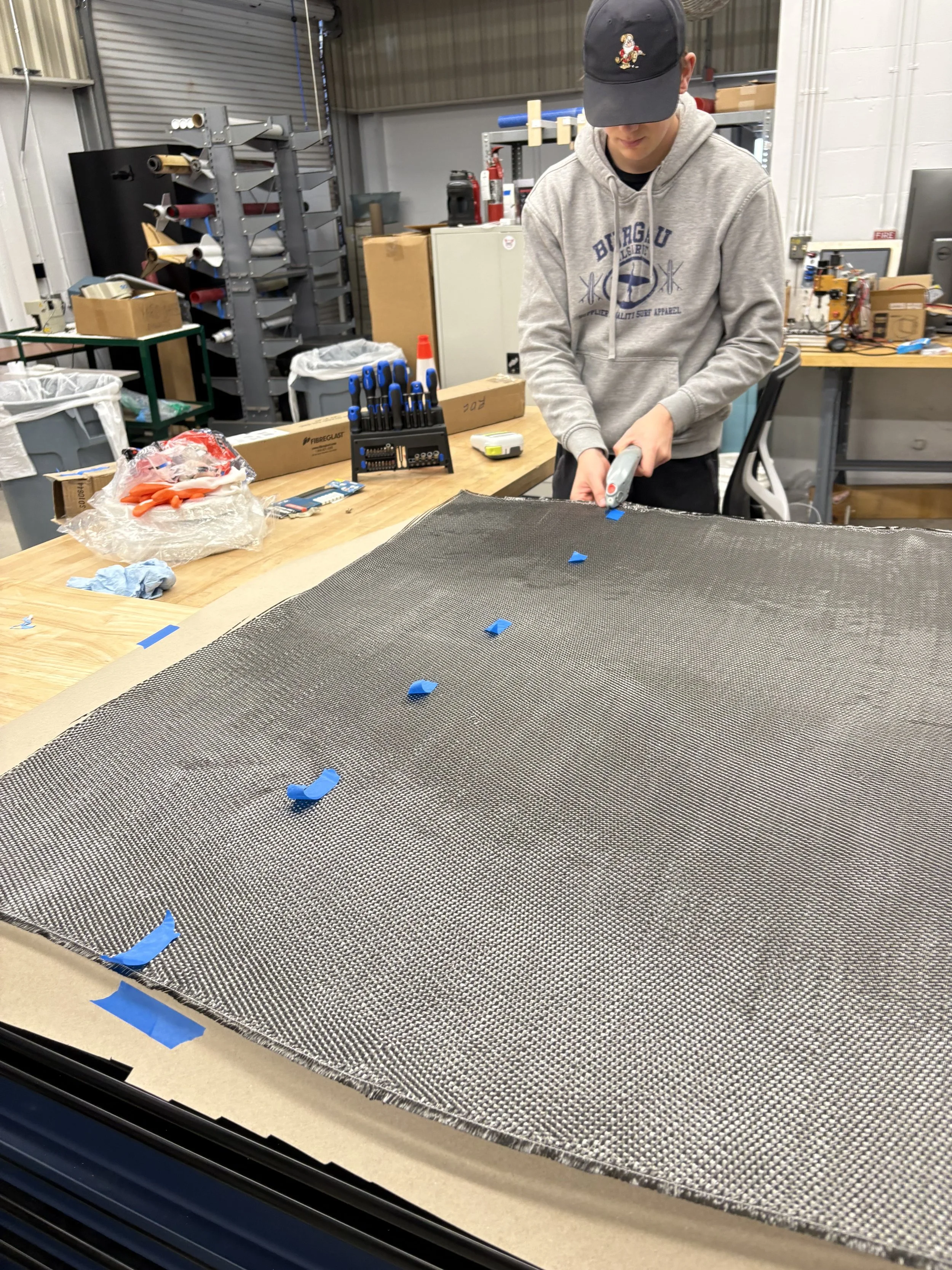
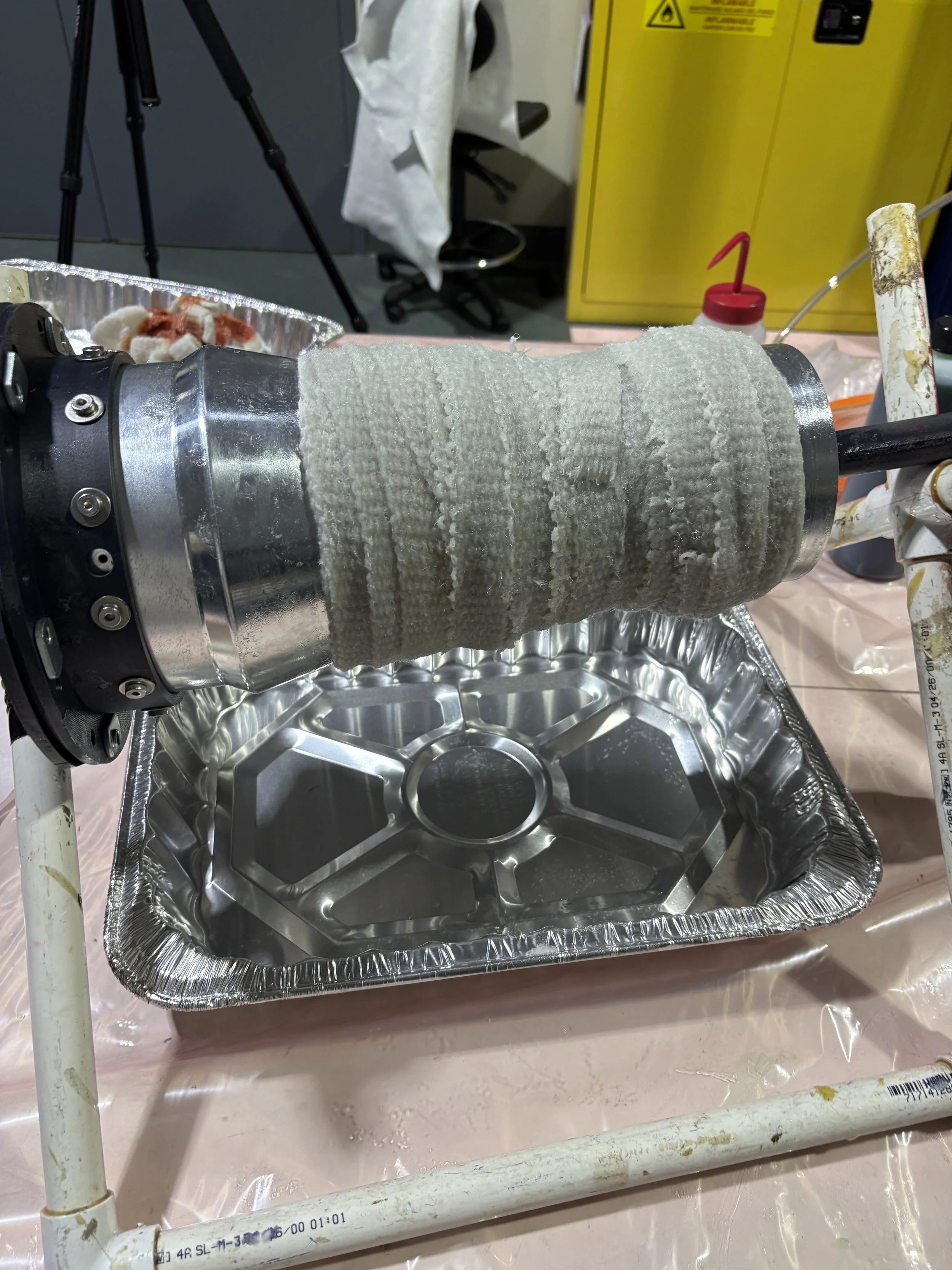
Luckily, we had been preparing for this scenario with the creation of a composite engine built to replace the old assembly. I am the lead of this project, and it has finally come to fruition, as within two weeks of the nozzle shearing, all components of the composite changeover were able to be machined, prepped, and put together for hot fire.